Electricity & Simple Circuits — Print · Grade 8 Science
Chapter: Energy & Heat TransferElectricity & Simple Circuits
Learning goals
- I can describe the parts of a simple circuit and the difference between series and parallel circuits.
- I can use Ohm's law (V = IR) to find voltage, current, or resistance.
- I can use circuit observations as energy-transfer evidence and distinguish series and parallel paths.
Readings for this unit
Before this unit
Distinguish a complete conducting path from an open path.
Use three teaching sessions of about 40–45 minutes: first observe the phenomenon, draft a model and study Parts 1–2; next explain Parts 3–4 with the figures and evidence; then work the application, examples, practice, model revision and exit check. Divide any difficult part into smaller steps and revisit after feedback. Investigations, review and quizzes have separate sessions. Study the four visual parts across the scheduled sessions, then use the illustrated worked case and independent transfer questions. Extend or revisit a session when the learner cannot explain the figure; completion time is a proposed allocation, not a mastery guarantee.
Start with something to explain
What would explain the observations in electricity & simple circuits?
Illustrative evidence case. Illustrative 6 V circuits have resistances 3 Ω and 12 Ω in separate trials. A drawing omits the return connection to the battery.
Notice and wonder
What changes with a 12 Ω resistor at the same ideal voltage? Write two observations from the supplied record without guessing their cause. Include a quantity and its unit when given. An observation is what was recorded; an inference is what you think explains it.
Write one question about why the pattern occurs and one question about a comparison that could distinguish competing explanations. A testable question identifies what could be observed or measured.
Your first model
Before reading the model answer, sketch the named objects or particles and label what you think changes. Find currents under the simple Ohm’s-law model and repair the circuit drawing. Explain why current is not used up in a bulb. Keep this first version so you can compare it with your later explanation.
Build the language from the idea
- circuit
- A closed loop that allows electric current to flow from a power source, through a device, and back.
- current
- The flow of electric charge, measured in amps (A).
- voltage
- The electrical push (potential difference) that drives current, measured in volts (V).
- resistance
- Anything that opposes the flow of current, measured in ohms (Ω).
- series circuit
- A circuit with a single path, where a break anywhere stops the current everywhere.
- parallel circuit
- A circuit with multiple paths, where each device can work independently of the others.
- model
- A representation that explains selected features and makes predictions; it leaves other details out.
- evidence
- Relevant observations or records used to support or challenge a claim.
- system boundary
- The chosen limit separating the objects being studied from their surroundings.
- assumption
- A condition taken as true for a model or calculation and needing to be checked against the case.
A simple direct-current circuit provides a complete conducting path through a source and components. Current is rate of charge flow, measured in amperes. Opening a switch interrupts sustained current in the simple series path. Charge is already present in conducting materials, and the lamp does not use it up. The source supplies energy that transfers to components through electrical processes. The classroom steady-circuit model does not describe every brief transient during switching.
Two more quantities shape how a circuit behaves. Voltage, measured in volts (V), is the electrical 'push' — the pressure from the battery that drives the current forward. Resistance, measured in ohms (Ω), is anything that opposes or slows that flow. A water-pipe analogy helps: voltage is like the pressure pushing water through a pipe, current is how much water actually flows, and resistance is like a narrow section of pipe that holds the flow back. A thin wire or a bulb's glowing filament adds resistance the way a pinched hose slows water.
For an ohmic component under stated conditions, V=IR relates its potential difference, current, and resistance. With a fixed ideal voltage source and a constant resistor, increasing resistance reduces current. Real lamps and other devices may not maintain constant resistance as temperature or operating conditions change. Use the supplied model and measured conditions rather than treating one fixed resistance as a universal description of every electrical device.
How a circuit is wired changes everything, too. A series circuit provides just one single path for the current to follow. That makes it simple, but fragile: if the path breaks anywhere — one bulb burns out, one connection comes loose — the whole circuit goes dead, because there's no other route for the charge. Old-style holiday light strings were notorious for this, where a single dead bulb left the entire strand dark.
A parallel circuit solves that problem by offering several separate paths at once. Since each device sits on its own branch, current can still reach the others even if one path is broken, so each device works independently. This is how the wiring in your home is built: you can switch off a single lamp, or have one appliance fail, without cutting power to the rest of the house. That independence is exactly why parallel wiring is used almost everywhere it counts.
Putting these ideas together explains a lot of the technology you rely on every day. Ohm's Law predicts how much current a device will draw, which is why fuses and circuit breakers are built to cut the power if the current ever climbs dangerously high and threatens to overheat the wires. From the phone charging in your hand to the entire electrical grid, it all comes back to the same handful of ideas: a complete circuit, a voltage to push the current, resistance to control it, and a smart choice between series and parallel paths.
A circuit needs a complete path and a source providing an electric potential difference. Charge is already present in the wires; it is not used up by a lamp. Energy is transferred from the source through the circuit to components.
In a series circuit the same current passes through each component. Parallel branches provide more than one path; the voltage across branches connected to the same two points is equal. Adding a parallel branch can increase total current drawn from an ideal source.
Use only low-voltage classroom cells for investigations. Never connect the terminals directly with a bare wire because a short circuit can heat the wire or battery. Draw the path, predict the result and then use an adult-approved setup to check it.
Build your understanding
Where this fits
This unit helps answer the chapter question: Where does energy go, and how can we control its transfer? Keep a notebook table with the question, evidence, explanation and one unresolved issue. Revise a previous model only when you can name the new evidence or idea that changes it.
Use three teaching sessions of about 40–45 minutes: first observe the phenomenon, draft a model and study Parts 1–2; next explain Parts 3–4 with the figures and evidence; then work the application, examples, practice, model revision and exit check. Divide any difficult part into smaller steps and revisit after feedback. Investigations, review and quizzes have separate sessions.
Part 1 · Trace a complete conducting path
A simple circuit needs a continuous conducting path through source and components. Opening a switch breaks the path and stops sustained current in the simple circuit. A battery supplies energy through an electrical interaction; it does not send light-making particles that are used up in the bulb.
Read the visual model
Why does an open switch stop the lamp in a simple series circuit?
Visual reasoning — after your attempt
It breaks the conducting loop. Sustained current cannot continue through the complete source-lamp path in this simple model.
Trace the path from one battery terminal through a lamp and back to the other terminal. A wire connected to only one side of the lamp is not a complete loop. Use circuit symbols to show connections rather than judging whether components look close together.
Pause and explain
Why does an open switch stop the lamp in a simple series circuit?
Check your reasoning after answering
It breaks the conducting loop. Sustained current cannot continue through the complete source-lamp path in this simple model.
Part 2 · Separate current from potential difference
Current is rate of charge flow, measured in amperes. Potential difference, or voltage, describes energy transferred per unit charge, measured in volts. Resistance relates them for an ohmic component under stated conditions: V=IR. The two quantities are not interchangeable, and real bulbs can change resistance as they warm.
Read the visual model
A coulomb (C) is a unit of electric charge; an ampere (A) is one coulomb per second, and a volt (V) is one joule per coulomb. Introduce these units before using their ratios. The diagram uses a safe supplied-data circuit, not mains wiring.
What current and potential difference follow from the two records, and why are they different quantities?
Visual reasoning — after your attempt
Current = 4 C/2 s = 2 A; potential difference = 12 J/4 C = 3 V. One is charge-flow rate and the other energy transferred per charge.
For a supplied constant resistor of 6 Ω with 3 V across it, I=V/R=0.5 A. This calculation assumes the stated resistance remains suitable under the test conditions. It is not a universal rule that every component has one fixed resistance.
Pause and explain
Why should a lamp not automatically be treated as a constant resistor?
Check your reasoning after answering
Its filament temperature can change during operation, changing resistance. The fixed-resistance model needs a stated condition or supplied approximation.
Part 3 · Compare series and parallel connections
In series, components share one unbranched path and have the same current. In parallel, branches connect across common points and can have the same potential difference. Current divides among branches and recombines. Opening one series path can stop all its lamps; opening one parallel branch need not stop the others.
Read the visual model
A lamp symbol is a circle with a cross. Lines represent conducting connections, not the flow of a substance called electricity. Trace from one supply terminal through a complete branch back to the other before making a current claim.
Why can the other parallel lamp remain lit when one branch opens, while a series lamp may not?
Visual reasoning — after your attempt
The remaining parallel branch still provides a complete route across the supply. In series, opening the only route prevents current through both lamps.
Draw connections as junctions, not crossings that merely overlap on paper. For two parallel branches carrying 0.2 A and 0.3 A, total current into the junction is 0.5 A in the steady model. Charge is not consumed at the junction.
Optional guided lab · Compare complete paths in a circuit
Optional guided lab · Compare complete paths in a circuit
Optional external exploration — WeduLab. Complete the local explanation first. The task and practice record here are independently written for this course. Choose this in place of comparable practice or allow extra time; it does not add a required session to the year plan.
Predict: with the same ideal battery and two identical fixed resistors, will each parallel branch have more or less current than the series path? Draw both complete circuits before opening the lab. Current is charge passing a point per second; potential difference is energy transferred per unit charge.
Explore for about 15–20 minutes after the circuit explanation. Use the series/parallel topic or blank workbench, choosing fixed resistors if available. Keep source voltage and resistor values constant. Record the connection, voltage across each resistor and current in each path. Open one branch and compare the remaining path. If meters or exact values are unavailable, use the supplied model below; do not invent measurements.
This is a virtual circuit activity. Lamp filaments need not have constant resistance, and a real battery has internal resistance and limited current. The supplied calculations assume fixed ohmic resistors and an ideal 1.50 V source. They do not authorize constructing short circuits with real batteries.
No-lab route: the original supplied record below contains everything needed for the question. It is not measured evidence collected from WeduLab. Label any separate observations you collect as simulation output, with settings and date.
| Connection — original ideal model | Source voltage / V | Resistance of each resistor / Ω | Current through each resistor / A |
|---|---|---|---|
| One resistor | 1.50 | 3.00 | 0.50 |
| Two in series | 1.50 | 3.00 | 0.25 |
| Two in parallel | 1.50 | 3.00 | 0.50 |
Question 1
Explain why the two series resistors carry 0.25 A each, while each parallel branch carries 0.50 A. Find the total source current in the parallel circuit. What changes if one parallel branch opens in this ideal model?
Worked solution and marking guidance
Series resistance is 3.00 + 3.00 = 6.00 Ω, so I = 1.50/6.00 = 0.25 A. The same current passes through both series elements.
Each parallel branch has the full 1.50 V across 3.00 Ω, giving 0.50 A. Branch currents add at the source.
Opening one branch removes that current path. With the ideal source voltage unchanged, the other branch still carries 0.50 A.
Parallel source current is 1.00 A before opening a branch and 0.50 A afterward. The remaining branch stays at 0.50 A in the ideal model. Current is not used up in a resistor; energy is transferred.
- Draw complete conducting paths and identify which voltage is held constant.
- Use resistance and branch-current reasoning with units.
- Distinguish the ideal source from a real battery and do not treat model values as laboratory measurements.
Pause and explain
How does current entering a steady junction compare with current leaving?
Check your reasoning after answering
The total entering current equals the total leaving current, accounting for all branches. Charge does not continually accumulate at the junction in the steady model.
Part 4 · Trace energy and keep low-voltage work controlled
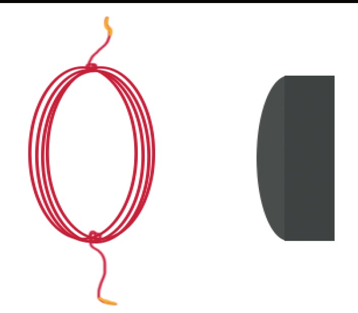
A battery’s chemical store decreases as energy is transferred to circuit components and surroundings. Current need not decrease after a lamp as if energy and charge were the same quantity. Circuit investigations should use approved low-voltage sources and avoid short circuits, which can produce excessive heating.
Read the visual model
Why is a short circuit different from a proper lamp connection?
Visual reasoning — after your attempt
It provides a very low-resistance path that can draw excessive current and heat components. It bypasses the intended controlled energy transfer.
Use supplied diagrams and measurements, or an approved battery kit with adult guidance. Never connect to wall outlets or improvise with damaged batteries. A wire directly across battery terminals bypasses useful resistance and is not an acceptable demonstration of a lamp circuit.
Pause and explain
Why is a short circuit different from a proper lamp connection?
Check your reasoning after answering
It provides a very low-resistance path that can draw excessive current and heat components. It bypasses the intended controlled energy transfer.
Observe energy transfer in circuit paths
A circuit diagram should be tested against device behavior, especially when a connection is opened.
A circuit is a complete conducting path in which charge can move. Current is the rate of charge flow; voltage is energy change per charge between specified points. A source transfers energy, and a lamp receives electrical energy and transfers it into light and thermal pathways. Charge is not used up as it passes a lamp. A visible response is evidence of energy transfer, but brightness alone does not measure current or total energy exactly.
A series arrangement places devices on one continuous path. Opening that path prevents the sustained circuit current in this introductory model, so both lamps stop operating. A parallel arrangement has separate branches across the source. Opening one independent branch can leave a different complete branch operating. This assumes the source and components can function under those conditions; actual brightness and source voltage can depend on loading.
Plan observations with diagrams and matched components before constructing anything. Compare closed and open paths, record each lamp’s state, and draw energy arrows separately from charge-flow arrows. If safe equipment is not available, analyze the supplied observation table without calling it personally measured. An actual investigation must document its real setup and outcomes. Never infer safety for a wall-powered circuit from these low-voltage classroom models.
Evidence to interpret
| Supplied arrangement | Connection change | Lamp record |
|---|---|---|
| Series | Loop closed | Both respond |
| Series | One path opened | Both stop |
| Parallel | Only branch A opened | A stops; independent B responds |
Use this method safely
No mains outlets, improvised exposed wiring, disassembly or short circuits. Optional real observations use an approved enclosed low-voltage educational kit under adult guidance; follow its instructions and disconnect if components warm unexpectedly.
Investigate or evaluate the supplied records
- Draw source, lamps and return paths for both arrangements.
- Use provided observations or an adult-approved enclosed low-voltage educational kit with correctly rated parts.
- Record lamp behavior before and after the intended connection change, keeping the other components comparable.
- Add energy-transfer arrows and distinguish them from current direction.
- Repeat, report actual observations honestly and explain deviations from the simple model.
Explain and apply
Complete source/return diagrams, compare the three supplied records and explain evidence for energy transfer by current. Identify which observations would be needed to measure energy quantitatively.
- Complete conducting paths and distinguish arrangements.
- Use observed device behavior as qualitative evidence.
- Separate charge, energy and measurement limits.
Reasoning and marking guidance — after your attempt
With the supplied series loop closed, both lamps respond; opening the single path makes both go out. In the parallel model, opening one branch leaves the other complete branch operating. Light/thermal responses provide qualitative energy-transfer evidence, not charge consumption. Quantitative energy needs voltage, current and duration or another justified method, not brightness alone.
Apply the whole unit · Analyze a parallel circuit record
Illustrative low-voltage circuit: a 3 V source supplies two parallel branches. Branch A contains a constant 6 Ω resistor; branch B contains a constant 12 Ω resistor. Ignore source and wire resistance.
Your task
Draw the circuit, calculate each branch current and total source current, and predict what happens to A if B’s branch switch opens under the ideal-source assumption. Explain the distinction between current and transferred energy.
What your response should show
- Use the supplied observations and measurements accurately; include units where needed.
- Explain the science behind your answer, rather than giving only a number or label.
- Show a labeled model, calculation, or evidence comparison as requested.
- State an assumption or limitation and suggest a useful next measurement.
Response guidance — after your attempt
Both branches have 3 V. A draws 3/6=0.5 A; B draws 3/12=0.25 A; source current is 0.75 A. Opening B leaves A at 0.5 A with an ideal 3 V source; real source behavior may differ. Charge flows around paths while energy transfers from the battery to components. Current is not consumed as energy in a resistor.
Scientific references and adapted teaching resources
- OpenSciEd 6.2 Thermal Energy — public unit overview
- OpenSciEd 8.3 Forces at a Distance — public unit overview
- OpenSciEd instructional model — storyline routines
- Creative Commons Attribution 4.0 — middle-school material license
Parent / teacher teaching notes
Use connection tracing before arithmetic. Keep this as supplied-data work unless an approved low-voltage kit is available. Check series/parallel distinctions and the difference between charge flow and energy transfer. Adaptation credit: OpenSciEd middle-school teaching routines and public task structures by OpenSciEd, CC BY 4.0. This independent version adds original explanatory text, data and figures, terminology support and a home-study schedule. It does not reproduce the complete teacher editions or their classroom validation. The illustrated study “Observe energy transfer in circuit paths” is required curriculum content. Teach it before the associated application or distribute it over the assigned unit sessions; it is not an optional enrichment. Its practice/review/quiz response provides evidence of understanding. Model/data work must not be recorded as an actual physical experiment.
The key idea
Ohm's Law connects voltage, current, and resistance: V = I × R; series circuits share one path, parallel circuits offer independent paths.
Ohm's Law
V = IR
V is voltage in volts (V); I is current in amps (A); R is resistance in ohms (Ω). Rearranges to I = V ÷ R or R = V ÷ I.
Worked examples
Example 1
- Rearrange V = IR to solve for current: I = V ÷ R.
- I = 12 ÷ 4.
- = 3.
Example 2 · Worked application
- Rearrange R=V/I.
- Substitute 6/0.5.
- Voltage is in volts and current in amperes, giving ohms.
Check 0.5×12=6 V.
Example 3
- Use V = IR.
- V = 2 × 5.
- = 10.
Example 4
- Breaking the series path stops current through both bulbs.
- Opening one parallel branch can leave the other branch's complete path intact.
Example 5 · Find and fix the mistake
- Test the claim against the stated conditions: Check 0.5×12=6 V.
- Charge is conserved; steady current is the same around one unbranched loop. Energy is transferred in components.
Check 0.5×12=6 V.
Example 6 · Interpret the visual model
- Identify the represented objects, axes, labeled quantities and stated conditions before choosing a rule.
- A coulomb (C) is a unit of electric charge; an ampere (A) is one coulomb per second, and a volt (V) is one joule per coulomb. Introduce these units before using their ratios. The diagram uses a safe supplied-data circuit, not mains wiring.
- Current = 4 C/2 s = 2 A; potential difference = 12 J/4 C = 3 V. One is charge-flow rate and the other energy transferred per charge.
Keep the model’s stated limits explicit: This conceptual closed circuit separates a supplied charge-flow record, 4 coulombs in 2 seconds, from a supplied energy-per-charge record, 12 joules for 4 coulombs across the receiver. They give 2 A and 3 V respectively. The arrow follows conventional current rather than a drawn individual electron path. Charges circulate; a lamp transfers energy rather than using up the charge itself.
Avoid these mistakes
- A bulb uses transferred energy, not a supply of charge that disappears.
Check your understanding
Two bulbs are in series and one connection is removed. What happens? Compare with two independent parallel branches.
Discuss the answer
Both series bulbs go out; a bulb in the other intact parallel branch can stay lit.
Why is a direct wire across a battery unsafe even at low voltage?
Discuss the answer
A circuit needs a complete path and a source providing an electric potential difference. Charge is already present in the wires; it is not used up by a lamp. Energy is transferred from the source through the circuit to components. In a series circuit the same current passes through each component. Parallel branches provide more than one path; the voltage across branches connected to the same two points is equal. Adding a parallel branch can increase total current drawn from an ideal source.
Return to the phenomenon
Illustrative 6 V circuits have resistances 3 Ω and 12 Ω in separate trials. A drawing omits the return connection to the battery. Find currents under the simple Ohm’s-law model and repair the circuit drawing. Explain why current is not used up in a bulb. Revise your first explanation using a named idea from the lesson. Mark the changed part and the evidence that supports it.
Compare explanations after your attempt
Currents are I=V/R=2 A and 0.5 A for the respective simple resistors. Add the continuous return path; an open circuit does not sustain the modeled current. Energy is transferred to the bulb and surroundings, while charge is not consumed. This is a model using ideal sources and appropriate resistive components, not every real device.
What should we investigate next?
Which condition could be changed to test a remaining uncertainty in this explanation? State the predicted observation and what result would challenge your model.
Investigate, explain and revise
Use these tasks after the three teaching sessions as needed. Discuss an attempted explanation before opening response guidance; a matching sentence is less important than a supported mechanism.
Activity 1 · Explain the new evidence case
Use the visible scenario above, Parts 1–4 and your first notebook model. No outside reading or equipment is required.
Your task
Illustrative 6 V circuits have resistances 3 Ω and 12 Ω in separate trials. A drawing omits the return connection to the battery. Find currents under the simple Ohm’s-law model and repair the circuit drawing. Explain why current is not used up in a bulb. Write 100–150 words or give a labeled drawing with an equivalent oral explanation.
Success criteria
- Use two relevant stated records or conditions.
- Explain the mechanism rather than only repeat a definition.
- Label observation and inference.
- Name a changed model feature or a remaining uncertainty.
Hint
Read the stated boundary and conditions before selecting a relationship. The unit’s worked examples show intermediate steps.
Response guidance — discuss after your attempt
Currents are I=V/R=2 A and 0.5 A for the respective simple resistors. Add the continuous return path; an open circuit does not sustain the modeled current. Energy is transferred to the bulb and surroundings, while charge is not consumed. This is a model using ideal sources and appropriate resistive components, not every real device.
Activity 2 · Read and extend the figure
Study the new labeled figure and its caption, then compare it with the associated teaching part.
Your task
What changes with a 12 Ω resistor at the same ideal voltage? Explain what each important label represents. Add one missing feature that would be needed for a different question, and explain why the original figure leaves it out.
Success criteria
- Answer the figure question with its stated labels.
- Connect the visual representation to the scientific idea.
- Identify a specific limitation from the caption.
- Propose a useful change without misrepresenting supplied evidence.
Hint
The simple model has a complete source–resistor–return loop and uses Ohm’s law for an appropriate ideal resistor. It is not a wall-electricity construction instruction. Current is charge flow and is not consumed by the resistor; energy transfers into thermal pathways.
Response guidance — discuss after your attempt
The modeled current is 6/12=0.5 A; the complete return path remains required. The simple model has a complete source–resistor–return loop and uses Ohm’s law for an appropriate ideal resistor. It is not a wall-electricity construction instruction. Current is charge flow and is not consumed by the resistor; energy transfers into thermal pathways.
Words to know
- circuit
- A closed loop that allows electric current to flow from a power source, through a device, and back.
- current
- The flow of electric charge, measured in amps (A).
- voltage
- The electrical push (potential difference) that drives current, measured in volts (V).
- resistance
- Anything that opposes the flow of current, measured in ohms (Ω).
- series circuit
- A circuit with a single path, where a break anywhere stops the current everywhere.
- parallel circuit
- A circuit with multiple paths, where each device can work independently of the others.
- model
- A representation that explains selected features and makes predictions; it leaves other details out.
- evidence
- Relevant observations or records used to support or challenge a claim.
- system boundary
- The chosen limit separating the objects being studied from their surroundings.
- assumption
- A condition taken as true for a model or calculation and needing to be checked against the case.
What's actually moving in a wire? (It's slower than you think)
Flip a switch and a light across the room turns on almost instantly — which makes it easy to assume electrons are zooming through the wire at incredible speed. In reality, individual electrons drift through a typical wire at a sluggish pace, often just fractions of a millimeter per second. What actually moves at a large fraction of the speed of light is the electric field throughout the entire circuit, nudging electrons everywhere along the wire to start shuffling forward almost simultaneously — like a tube already packed full of marbles, where pushing one marble in at one end instantly pops a different marble out the other end, even though no single marble traveled the whole tube's length.
Ben Franklin's unlucky guess
In the 1750s, Benjamin Franklin helped pioneer the study of electricity and introduced the labels 'positive' and 'negative' charge, guessing (with 50/50 odds) which type of charge actually flows through a wire. It later turned out that in metal wires, it's the negatively charged electrons that physically move, flowing from negative to positive — the opposite of Franklin's guess. But by the time scientists figured this out, the convention was already firmly in use everywhere, so today's textbooks and circuit diagrams still show 'conventional current' flowing from positive to negative, even though the actual electrons underneath are moving the other way.
Power, watts, and your electric bill
Multiplying voltage by current gives electrical power: P = V × I, measured in watts. Power companies bill customers using a related unit called the kilowatt-hour (kWh) — the energy used by 1,000 watts running continuously for one hour. A 100-watt light bulb left on for 10 hours uses 100 × 10 = 1,000 watt-hours, exactly 1 kWh. Every device in your home, from phone chargers to refrigerators, has a power rating, and multiplying that rating by however many hours it runs is exactly how your electric bill gets calculated.
Why fuses and breakers exist: current, resistance, and heat
Whenever current flows through resistance, some electrical energy converts into thermal energy — a process called resistive heating (or Joule heating), the same idea behind the glowing wire in a toaster. If too much current flows through a wire not designed to carry it, that resistive heating can raise the wire's temperature enough to melt insulation or start a fire. Fuses contain a thin strip of metal designed to melt and break the circuit if current gets dangerously high, while circuit breakers use a similar overheating (or a magnetic effect) to physically flip a switch — both are safety devices built entirely around the physics of heat transfer from Unit 4.
In the real world
Electricians use Ohm's Law every day to safely size wires and fuses for the amount of current a circuit will carry.
Exit check
What changes with a 12 Ω resistor at the same ideal voltage? Explain the relevant mechanism and one model limitation.
Check your explanation after answering
The modeled current is 6/12=0.5 A; the complete return path remains required. The simple model has a complete source–resistor–return loop and uses Ohm’s law for an appropriate ideal resistor. It is not a wall-electricity construction instruction. Current is charge flow and is not consumed by the resistor; energy transfers into thermal pathways.
Explain your reasoning without notes. If a key idea is missing, revisit the lesson and try again.
Problem 1
Answer and explanation
3 A
I = V ÷ R = 9 ÷ 3 = 3 A.
Problem 2
Answer and explanation
24 V
V = IR = 4 × 6 = 24 V.
Problem 3
Answer and explanation
3 Ω
R = V ÷ I = 15 ÷ 5 = 3 Ω.
Problem 4
- only that bulb goes out; the others stay lit
- all the bulbs go out because the circuit is broken
- the other bulbs get brighter
- nothing changes
Answer and explanation
all the bulbs go out because the circuit is broken
A series circuit has only one path, so a break anywhere stops current everywhere on that path.
Problem 5
- rubber
- glass
- copper
- wood
Answer and explanation
copper
Copper is a metal that conducts electricity very well, which is why it's used in wiring.
Problem 6
Answer and explanation
In a parallel circuit, each device, like a lamp or TV, has its own path, so if one device is switched off or stops working, the others keep getting power. That's why turning off one light at home doesn't turn off the whole house.
Problem 7
Answer and explanation
Both series bulbs go out; a bulb in the other intact parallel branch can stay lit.
Breaking the series path stops current through both bulbs.
Opening one parallel branch can leave the other branch's complete path intact.
Response criteria
- Use the stated conditions.
- Show the evidence or calculation.
- Explain the conclusion and any stated limitation.
Problem 8
Hints
Check 0.5×12=6 V.
Answer and explanation
I=V/R=9/18=0.5 A in the ideal model.
Problem 9
Hints
State what the supplied observations or conditions establish, and separate that from any assumption.
Answer and explanation
The gap breaks the continuous conducting path; charge cannot circulate steadily through that loop.
Problem 10
Hints
Use the illustrated study titled Observe energy transfer in circuit paths. Keep the observations, model and conditions separate.
Answer and explanation
With the supplied series loop closed, both lamps respond; opening the single path makes both go out. In the parallel model, opening one branch leaves the other complete branch operating. Light/thermal responses provide qualitative energy-transfer evidence, not charge consumption. Quantitative energy needs voltage, current and duration or another justified method, not brightness alone.
With the supplied series loop closed, both lamps respond; opening the single path makes both go out. In the parallel model, opening one branch leaves the other complete branch operating. Light/thermal responses provide qualitative energy-transfer evidence, not charge consumption. Quantitative energy needs voltage, current and duration or another justified method, not brightness alone.
Response criteria
- Complete conducting paths and distinguish arrangements.
- Use observed device behavior as qualitative evidence.
- Separate charge, energy and measurement limits.
Problem 11
Answer and explanation
Current = 4 C/2 s = 2 A; potential difference = 12 J/4 C = 3 V. One is charge-flow rate and the other energy transferred per charge.
A coulomb (C) is a unit of electric charge; an ampere (A) is one coulomb per second, and a volt (V) is one joule per coulomb. Introduce these units before using their ratios. The diagram uses a safe supplied-data circuit, not mains wiring.
Current = 4 C/2 s = 2 A; potential difference = 12 J/4 C = 3 V. One is charge-flow rate and the other energy transferred per charge.
Response criteria
- Use the named labels, directions or supplied quantities accurately.
- Connect the visual evidence to the scientific mechanism or calculation.
- State the relevant model conditions or limitation.
Problem 12
Answer and explanation
Potential difference 18/6 = 3 V; current 6/3 = 2 A. Charge circulates through the complete circuit while energy is transferred to the receiver.
Use joules per coulomb for voltage and coulombs per second for current.
Keep conserved charge flow distinct from energy transfer.
Potential difference 18/6 = 3 V; current 6/3 = 2 A. Charge circulates through the complete circuit while energy is transferred to the receiver.
Response criteria
- Use the named labels, directions or supplied quantities accurately.
- Connect the visual evidence to the scientific mechanism or calculation.
- State the relevant model conditions or limitation.